Introduction to Distance Sensors (Stereo Camera, Projection, LiDAR)
This is an English translation of
It's mostly powered by DeepL, so don't count too much on the English.
Goals
While a normal camera extracts the brightness and color of an object, a distance sensor senses the distance to an object. This is why they are sometimes called 3D cameras or depth sensors.
Knowing the distance is important in a variety of applications, for example, in automated driving, it is essential to know the exact distance to the vehicle in front. In games and other applications, Kinect, which uses distance sensors to extract human movements, has expanded the range of games. Distance sensors are also important for surgical robots such as DaVinci to know the exact distance to the affected area.
It is difficult to visualize the dimensions and distance of a room in a photograph or floor plan, but 3D mapping allows you to map the room itself. ! image.png
This kind of mapping can be easily done with the new iPhone Pro using apps like Polycam, so if you have the device, give it a try!
And the age of 3D scanners in our pockets has begun! The iPhone 12 version of Polycam is now out on the App Store https://t.co/Oih4jQTTEc! Go forth and capture your world 🚀🎥! #iPhone12Pro #iPhone12ProMax pic.twitter.com/JY8LAEi5xk
— polycam (@PolycamAI) 2020年10月23日
This article lists the major types of distance cameras in the world, their overview, features, and products used.
The goal is to help you choose the right distance sensor for your R&D project, for example. I'm a LiDAR expert, so I'm not very familiar with camera-based methods, but I've also described the most frequently used distance sensors: stereo cameras and projection cameras.
You can also read more about point cloud deep learning here: aru47.hatenablog.com
Stereo Cameras
Overview
This is a distance sensor that is widely available on the market that is used in e.g. Subaru EyeSight and other industrial products.

This WhitePaper from ensenso is also a good reference.
Obtaining Depth Information from Stereo Images Vision.pdf)

The principle is the same as how we see things in three dimensions.
If you close your eyes alternately to the left and right and look at the monitor, do you see the shift from left to right?
The brain perceives the object with the larger shift as being closer and the object with the smaller shift as being farther away. This is the principle behind stereo cameras, and it can be said that the distance sensors that we use are also based on stereo cameras**.
A stereo camera can measure the distance to an object based on how far the pixels have shifted. The farther apart the cameras are, the greater the pixel shift relative to the object, and the more accurate the distance. On the other hand, the closer the cameras are to each other, the more difficult it is to measure the distance because there is almost no pixel shift. Increasing the number of pixels will, in principle, increase the range, but the downside is that the amount of signal processing increases exponentially.
The biggest challenge for stereo cameras is to determine if the two cameras are looking at the same object. This requires advanced image processing techniques and makes it very difficult to guess whether distant objects are really identical or not.
Reference: Obtaining Depth Information from Stereo Images
In addition, there must be no difference in height between the left and right images in order to adapt stereo vision. In order to adapt stereo vision, there must be no height difference between the left and right images, so pre-processing is required to remove camera distortion and calibrate (rectify) the height difference.
Features
While other distance sensors require special components (such as lasers), stereo cameras can be realized by using only two ordinary commercial cameras.
However, in order to measure the distance, the left and right cameras need to see (recognize) the same location of the same object, and it is difficult to measure the distance of distant objects. The disadvantage is that the housing becomes larger if you want to see farther**, because parallax is not created for distant objects unless the camera is set farther away like EyeSight, although the mathematical formula is omitted.
Products used.
1台の PC に4種類の RGB-D カメラをつないで同時キャプチャしてみた。左上 DepthSense DS325、右上 Kinect v2、左下 Kinect v1、右下 RealSense D435。こけて倒したのは D415 (今回は不使用)。 pic.twitter.com/n5h4P2MPZO
— 床井浩平 (@tokoik) 2019年5月30日
For commercial products, Intel's RealSense** comes with software (SDK) and is easy to try.
The RealsenseD435 can be purchased on Amazon for 24,000 yen.
Here is an example of the RealsenseD435 output.
- High accuracy can be obtained at short distances (1-3m).
- High resolution because it is camera based.
- Real-time (30FPS) operation even on a CPU
These are the features of the D435. I think it is the best choice for distance sensors for hobby use.
The RealsenseD400 series also has pattern projection, but it is mostly a stereo camera that is used for distance estimation (even if the projection is turned off, the picture remains almost the same, so it is just a supplementary function).
Pattern Projection Cameras
Overview
Pattern projection cameras are used in high-performance 3D cameras for industrial applications and iPhone FaceID.
It projects a known pattern onto an object (pattern projection) and uses signal processing to derive the distance between the camera and the object from the way it is distorted.
If you project a pattern of stripes onto an object like a helmet, you will see that the stripes are distorted depending on the height of the object. By reading and analyzing such distortions, the three-dimensional shape of the helmet can be determined.
The video below also explains how the iPhone FaceID works. It uses infrared light to emit a pattern all over the face, and is able to read the exact shape of the face. Since it sees the unevenness, it is difficult to fool FaceID, which makes the security stronger.
Compared to LiDAR, the components are simpler, so the price can be reduced.
Very high accuracy can be obtained for indoor use (mm~um accuracy).
On the other hand, outdoor use with a lot of external disturbance is difficult.
There are also many approaches that use both pattern projection and stereo vision.
Ensenso, a high-precision 3D camera often used in picking robots, provides both pattern projection and stereo vision. The advantage of this camera is that it can obtain a clean point cloud even for objects that are difficult to match, which stereo vision is not good at (for example, flat walls).
Products
iPhone
! Image result for iphone face id
FaceID is an active projection camera that is used for facial recognition on the iPhone.
Every time FaceID is used, the iPhone emits an infrared pattern.
In fact, the original technology evolved from Apple's acquisition of the company (PrimeSense) that developed the Microsoft KinectV1. It's called MiniKinect by those who know it. LOL.
Industrial Products (Ensenso, Keyence)
How to reconstruct objects with an Ensenso 3D camera and data comparison using HALCON image processing: 3D image processing detects irregularities or minimal deviations that are not even visible to human eyes. #demo #objectverification #3Dvision #qualitycontrol #industry40 pic.twitter.com/3p4EEurOUW
— IDS Imaging Development Systems GmbH (@IDS_Imaging) 2018年8月9日
There aren't many examples of industrial sensor outputs on the net, but they are mm-accurate and incomparable to Realsense (which is over-spec for hobby use).
They cost several million yen each.
They are often used for inspection in factories and for robotic products. If you go to an industrial exhibition, you'll often see one of these attached to a product, so look for it.
On the other hand, the projection can only be accurately read within a few meters, making it difficult to use outdoors. Basically, it is for indoor use.
- Keyence 3D Camera, Ensenso 3D cameras
Time of Flight LiDAR
How Time of Flight works
Camera-based distance sensors (stereo cameras, projections) and LiDAR are fundamentally different in principle.
On the one hand, LiDAR measures distance based on Time of Flight.
The principle is simple: a laser beam is emitted from the enclosure as shown in the figure below, and the time it takes for the laser to be reflected back to the object is measured. If the laser beam returns after 10 seconds and the speed of light is 1m/s for simplicity, the distance to the object is
(10s * 1m/s)/2 = 5m
and we know that the object is 5 meters away. This method of deriving the distance based on the time of flight is called Time of Flight.
Since the actual speed of light is very fast, 108m/s, the time it takes for the light to return is on the order of a few picoseconds or nanoseconds, so the circuit used to measure the time needs to be highly accurate.
The type of LiDAR which directly measures the return time of the laser pulse is also called a direct time of flight sensor. FIY, The Lidar in iPad Pro and iPhone is direct time of flight.
https://tech.nikkeibp.co.jp/atcl/nxt/column/18/00001/02023/?ST=nnm

Features
The most important features of LiDAR are
- High accuracy
- Long range
- Resistant to external disturbance (can be used outdoors)
- High price
High cost Since the distance is derived directly from the return time of a strong pulsed laser beam, it is difficult to introduce errors and is highly reliable. Since these features are difficult to achieve with a camera-based system, LiDAR is expected to be used mainly for detecting distant objects in automated driving, which is required to operate even in harsh conditions.
On the other hand, the cost of LiDAR is several to dozens of times higher than that of the camera type because it requires a scanning mechanism, laser emitter, laser receiver, and many other specialized elements.
Recently, Livox and other LiDARs costing less than $1k have begun to be mass-produced and used in many robots, so the days of being shunned because of their high price may be coming to an end.
Livox全ラインナップに対応した低速(<30km/h)Slamを公開しました。先日公開した高速SLAMはHorizonのIMU情報を使っていますが、本プログラムは点群だけで計算する汎用型です。低速AGV、マッピング、AR、VR等の開発にご利用ください。https://t.co/LKLGZYPTYA pic.twitter.com/zTnn2wYbZP
— Livox_JAPAN (@LivoxTech_JP) 2020年6月29日
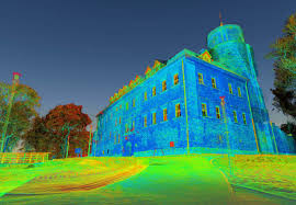
The greatest advantage of LiDAR is its ability to scan a fine point cloud over a long distance (100-200m) as shown in this figure.
LiDAR is the only distance sensor that can obtain a perfect point cloud over a long distance in the open air. This is why LiDAR is expected to be very popular in automated driving. (Although some people, such as Tesla, say they do not need LiDAR...)
Scanning LiDARs
It is possible to obtain the distance per pixel using the above-mentioned time of flight principle of LiDAR. But how can we get the distance information as a picture? To do this, LiDAR has a concept of scanning.
One approach is to use a mirror to scan (scan) the emitted laser beam.
The animation above is a clear representation of LiDAR scanning using a mirror. By rotating the mirror, the laser beam is scanned 360 degrees to obtain information on the entire surrounding environment.
A 2D raster scan is a method of scanning two-dimensionally while acquiring information one pixel at a time, while a 1D scan is a method of scanning horizontally while acquiring vertical pixels all at once. Both methods produce distance, but the 1D scan method is more likely to achieve a higher FPS because of the shorter time required to obtain a distance image.
On the other hand, using a mirror (like a single-lens reflex camera) will increase the size of the LiDAR housing. For this reason, MEMS mirrors are being used instead of mirrors, and Optical Phased Array LiDAR, which scans optically, is being actively developed, and it is expected that LiDAR will become smaller and less expensive in the future.
Flash LiDARs
LiDAR has also been developed to acquire two-dimensional pixel information at once, just like an image sensor of a camera, without scanning. This type of LiDAR is structurally very simple, as it only emits a laser beam that covers the entire image sensor and receives the light. Therefore, it can be realized at a lower cost than the scanning type.
On the other hand, there are several issues - Short distance due to low laser power per pixel - Susceptible to external disturbance - Susceptible to interference and noise Therefore, it is not suitable for automatic driving, but it may be useful for indoor robots.
Products
Velodyne Series
The most famous ToF LiDAR products are probably those of Velodyne, the first LiDAR manufacturer to introduce LiDAR products to the world and still the reigning "king".
Their products are notorious for being very expensive, ranging from hundreds of thousands to millions, but the quality is top-notch, and the only self-driving cars that don't use Velodyne are Tesla and Waymo (Waymo uses its own LiDAR). I also imagine that Velo is often used in robotics R&D because of its high pixel count and accuracy.
Livox Horizon
Livox, a subsidiary of DJI, has released a LiDAR that achieves high accuracy while costing less than $1k, and this is becoming the mainstream for robotics projects.
You can buy them in amazon as well..
The quality is great, and the SDK is available on github, so it's easy to develop.
iPhone
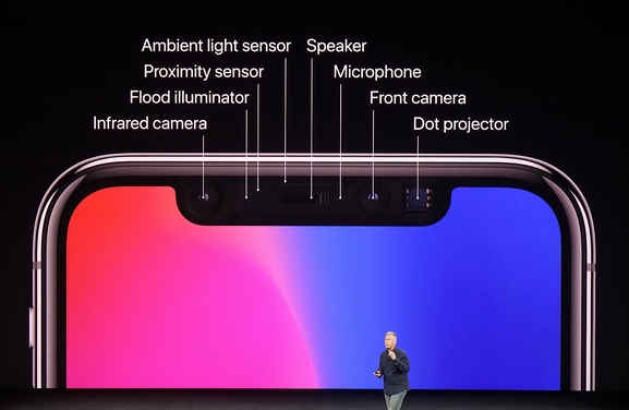 The front of the iPhone has actually been equipped with ToF LiDAR (one pixel) for quite some time.
It does not do any scanning, so it is probably low cost.
The front of the iPhone has actually been equipped with ToF LiDAR (one pixel) for quite some time.
It does not do any scanning, so it is probably low cost.
The Proximity Sensor in the image is the same. When you make a call, if you bring the iPhone screen close to your face, the screen will automatically turn off. I think this is because it senses the distance between your face and the iPhone.
Note: iPhone and iPad Pro are now equipped with dToF LiDAR.
iToF LiDAR
This technology is used in Azure Kinect and other applications.
点群DNN、3D DNN入門 -3DYOLO, VoxelNet, PointNet, FrustrumPointNet, Pointpillars
またまたQiitaからのお引越し記事です。
センサについてはこちらをどうぞ。
目的
点群データに対してディープニューラルネットワーク(DNN)を適応する研究は活発で、いくつものアプローチがあります。 大人気のPointNetだけではなく、他の手法も照らし合わせて各手法のメリット・デメリットを理解する自助をすることが記事の目的です。
浅く広く手法について学び、ああこういうアプローチがあるのかと気づくことができると幸いです。 各技術の詳細を知りたい場合は元論文や解説サイトを読むといいと思います。
またPointCloud DNNの論文についてはここにわかりやすくまとまっています。是非一読を!
点群DNNでできること
- 点群認識

与えられた点群が何の物体か認識するタスクです。 例えばShapenetにおいては点群がどの家具か当てるタスクがあります。 画像認識と同様のタスクです。
- 点群セグメンテーション
SUN-RGBDにあるタスクです。 点群がどの物体に属しているかセグメンテーションするタスクです。 画像セグメンテーションと同様のタスクです。
- 点群物体検出
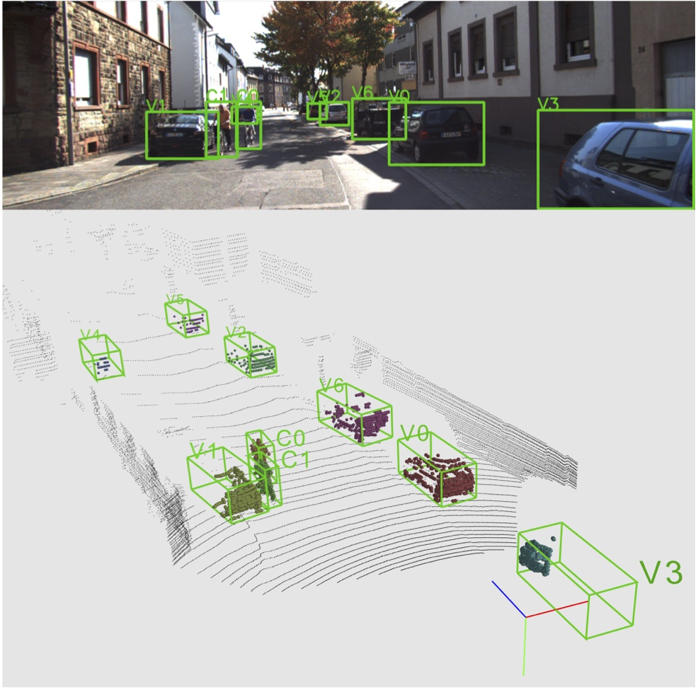 自動運転などに重要な点群中に存在する物体の座標を認識するタスクです。
アプリ的に需要が高く、一番研究としては人気のあるタスクな印象です。
自動運転などに重要な点群中に存在する物体の座標を認識するタスクです。
アプリ的に需要が高く、一番研究としては人気のあるタスクな印象です。
3Dセンサ
RealsenseD435はアマゾンで24000円と手頃でAPIも使いやすいです。
点群を取得してみたいのならば試しに買ってみてはいかがでしょうか。
3D DNNの家計図
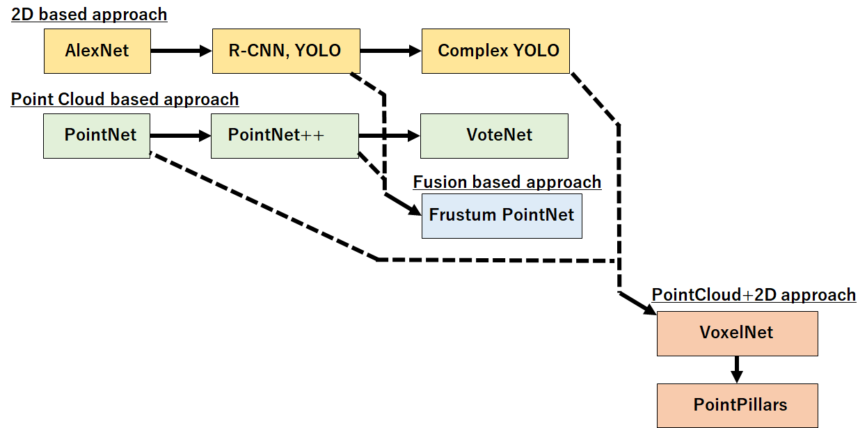
独断と偏見で3D DNN系の家系図を作ってみました。
大きくは * 2Dベースのアプローチを結集する2D based * あくまで点群にニューラルネットワークを適応するPoint cloud based approach * 画像から得た結果と点群ニューラルネットワークをフュージョンするアプローチ * また点群ニューラルネットワークで点群を前処理(エンコード)した後に2Dベースの物体検出を適応するPointCloud+2D アプローチ の四種類があると考えています。
それぞれを詳しく見てみましょう。
変更履歴
使うデータドメイン毎にカテゴライズを変更(2019/10/2) データセットなど加筆(2019/10/2) Pointpillars追加(2020/03)
2Dベースアプローチ
Complex YOLO (ECCV workshop 2018), YOLO 3D (ECCV workshop 2018)
Complex-YOLO: An Euler-Region-Proposal for Real-Time 3D Object Detection on Point Clouds
https://link.springer.com/chapter/10.1007/978-3-030-11009-3_11
YOLO 3D: End-to-end real-time 3D Oriented Object Bounding Box Detection from LiDAR Point Cloud
手法について
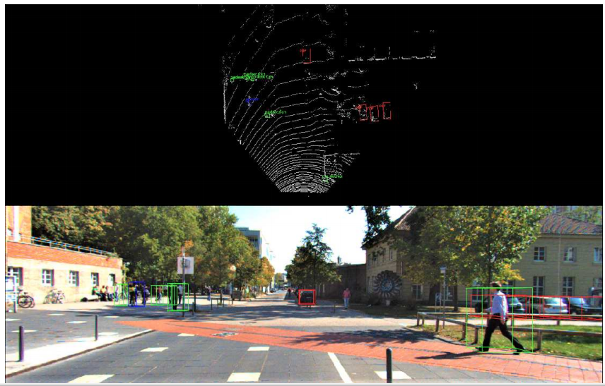
タスク:自動運転用の三次元物体検出 LiDARの点群はデータ量が少なく(疎)であるため、点群から物体の情報を直接抽出するのは難しい。
そこで点群を俯瞰的視点(上からみた)の画像を生成し、それに対し物体検出の手法(YOLOやFaster-RCNN)を適応するという手法です。 点群データも俯瞰視点に変換してしまえば車や人なども画像のように扱うことができます。 そのため成功をすでに収め、人間レベルの検出が可能なCNNを積極的に3Dの分野でも適応しようというのがベースの考え方です。
俯瞰(bird's eye viewまたはBEV)とは?
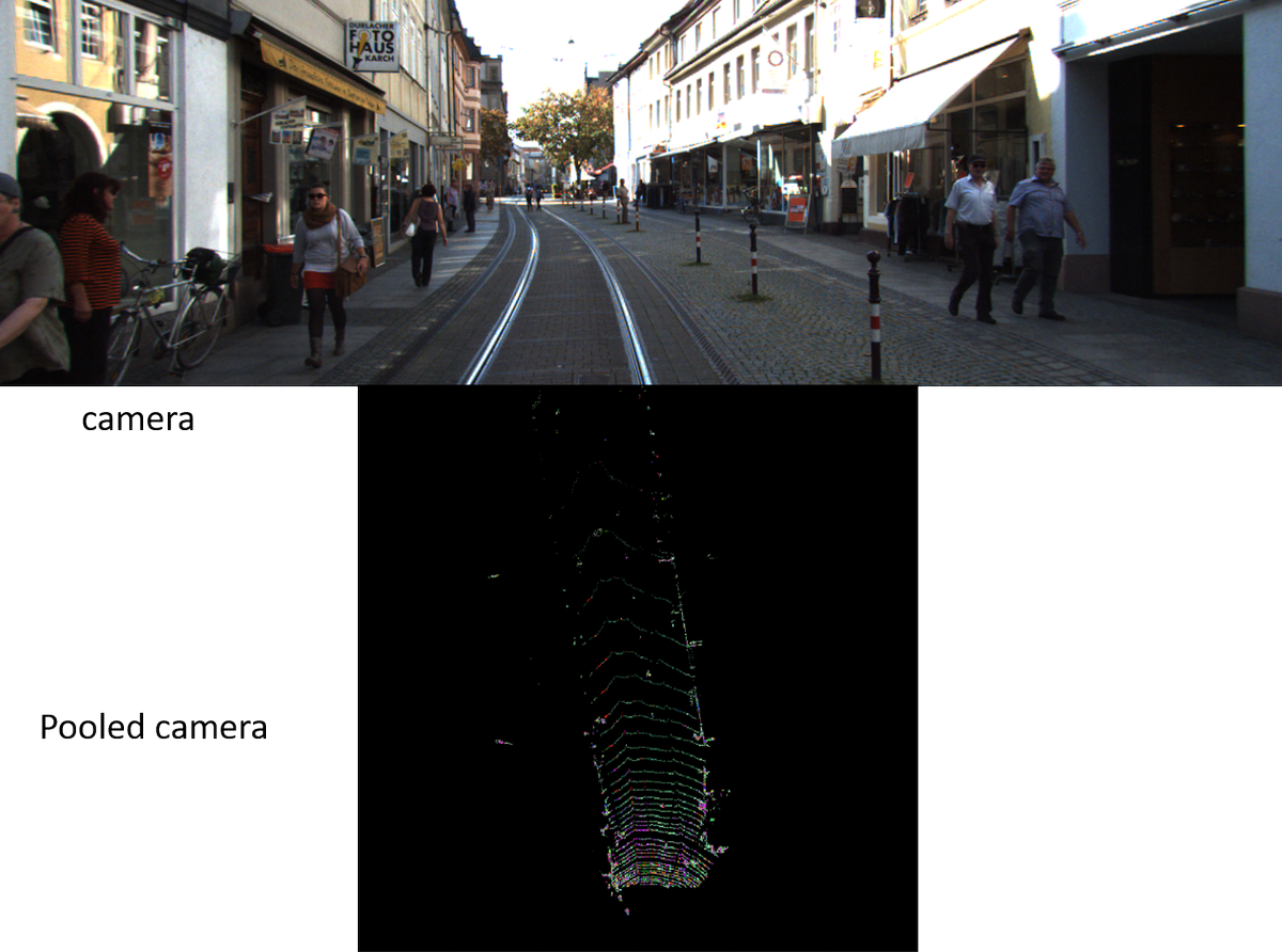 上の図が正面からみたカメラで下の図が俯瞰視点でみた点群です。
これを画像として扱い、物体検出DNNを適応します。
上の図が正面からみたカメラで下の図が俯瞰視点でみた点群です。
これを画像として扱い、物体検出DNNを適応します。
メリット
2D画像で成功したディープなR-CNNベースの手法をそのまま点群データに対し適応することができる。
R-CNNはImageNetやMS-COCOなどから転移学習できるので、必要な学習データ量が少なく済む可能性がある。
YOLOベースのため高速。リアルタイム動作も可能。
デメリット
点群を二次元化してしまうので物体の三次元的特徴(凸凹など)は読み取れない。
多角的に検出を行うことは可能だが、角度間(例えば俯瞰と正面)の検出結果の整合性を取るのが難しく検出を間違えたりしてしまう。
(あと3D研究者からすると手法がストレート過ぎておもしろくない笑)
点群ベースアプローチ (PointNet系)
PointNet(NIPS 2016)
PointNet: Deep Learning on Point Sets for 3D Classification and Segmentation
https://arxiv.org/abs/1612.00593
みんな大好きPointNet。
https://www.slideshare.net/FujimotoKeisuke/point-net
https://qiita.com/KYoshiyama/items/802506ec397559725a1c
に詳しい解説があるのでそちらも読むことをおすすめします。
PointNetの手法について

点に対し全結合ネットワークを複数回かけ合わせ、特徴量を抽出していく(Classification Network)。
そして最終的に得られた点に対する特徴量(n*1024部)をmaxpoolingすることで点群全体の特徴量(global feature)を得る。
点に対する特徴量抽出後、maxpoolingで全体特徴量を得ることが出来ることを示したのがPointNet最大の功績じゃないかと考えている。これでいいんだ!!という感じ。。笑

点群に対するクラス分類、セグメンテーション両方に対して(ModelNet,SUNRGB-D)非常に高いスコアを叩き出した。
PointNetのタスク
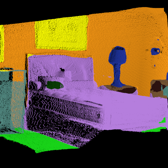
PointNetが効果を発揮するのはデータセットは主に室内で取られた点群データに対してです。
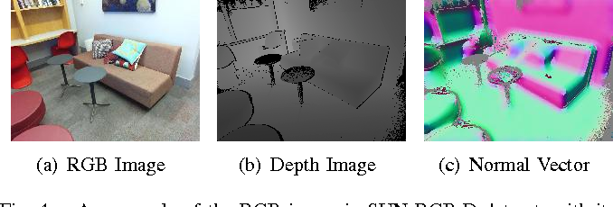
報告されているのは室内のセグメンテーションを行うSUNRGB-Dデータセット(上図)
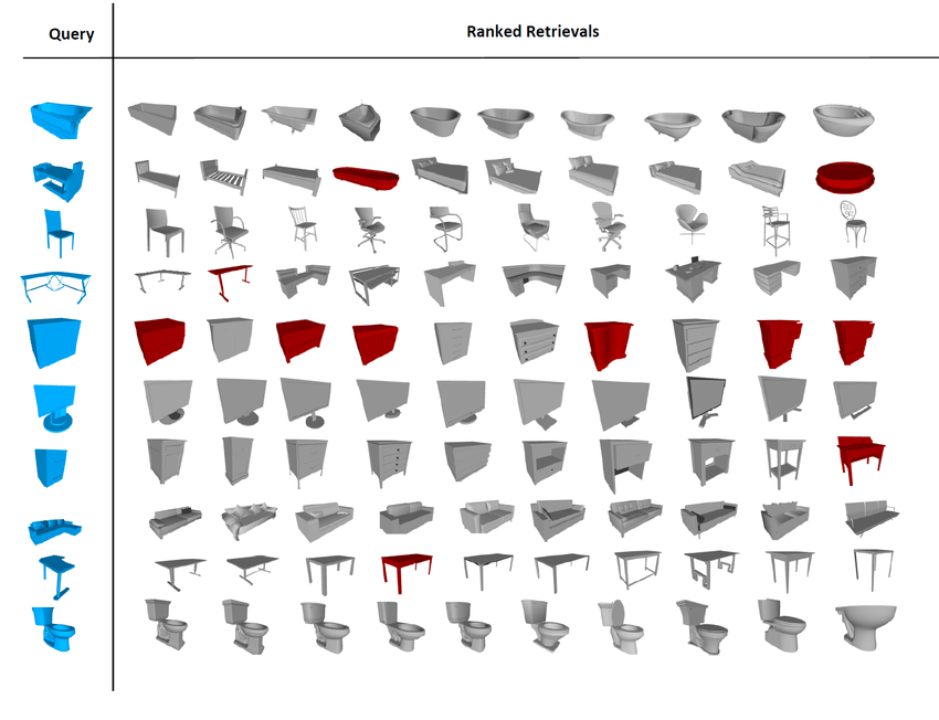
そして家具単体のクラスを当てるModelNet40です。
自動運転のようなKittiデータセットに対しては点群が疎すぎるため、適応できないとのこと。 これは後に2Dと3DをフュージョンするFrustrum PointNetで解決されました。
PointNetの実装
PointNet-Tensorflow(本家) https://github.com/charlesq34/pointnet
PointNet.Pytorch(自分もこれを使っており、本家同等の精度が出るのを確認してます) https://github.com/fxia22/pointnet.pytorch
PointNet-Keras https://github.com/garyli1019/pointnet-keras
PointNet-Chainer https://github.com/corochann/chainer-pointnet
PointNet++(NIPS 2017)
PointNet++: Deep Hierarchical Feature Learning on Point Sets in a Metric Space https://arxiv.org/abs/1706.02413
PointNetの局所的特徴を見ていない(近傍点群の情報を取り込めない)、という課題を改良したPointNet++も人気と実力が高いです。
PointNetに入力する点群を事前にクラスタリングした近傍点を入力することで、擬似的に局所的特徴量も抽出できるようになっています(後日加筆します。。)
まずはとっつき始めるならばPointNet,研究を行うならばPointNet++を元に実装を行うべきと思います。
実装
PointNet++.pytorch https://github.com/erikwijmans/Pointnet2_PyTorch
VoteNet(ICCV 2019)
Deep Hough Voting for 3D Object Detection in Point Clouds http://arxiv.org/abs/1904.09664
PointNet生みの親からの室内のオブジェクトの3D物体検出に向けた最新論文。 現在ScanNetv2ベンチマークにおいてSoTA。
点群の物体検出タスクは複雑な実装が多く、精度もあまり出ていなかった。 一方VoteNetはシンプルなアイデアながら、高い精度を実現。 基本的なアイデアは物体の中央をhough-votingで予測し、予測した中心点を元に物体検出するというもの(後日加筆します)。
今後人気が出てくるようと思うので要ウォッチ。
センサフュージョンベースアプローチ
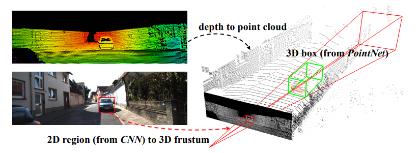
Frustrum PointNets
Frustum PointNets for 3D Object Detection from RGB-D Data
https://arxiv.org/abs/1711.08488
手法について
PointNetでは物体検出のタスクにはあまり向かない。
そこでカメラとLiDARデータのセンサフュージョンを行い、精度向上を達成。
そこで成功を収めている2DベースR-CNNで物体のある方向を円錐で絞り込んでから、その部分の点群のみPointNetにかけることで高精度な3D物体検出を実現。
これもアイデアは非常に単純だが、効果絶大なアプローチである。自動運転用など高い精度が求められる三次元物体検出を行うならばこのアプローチが一番スタンダードなのではないだろうか。
3D bindingbox predictionを行うPointNetも新規に提案している。

メリット
カメラ+LiDARを用いた3次元物体検出のタスクにおいてstate-of-the-art。(Kittiデータセット)
有力な2つの手法を組み合わせているので実装がしやすい。
デメリット
モデルを縦続的に使うので演算量は多い。
そもそもカメラで取り逃した物体は検出できない。
実装
https://github.com/charlesq34/frustum-pointnets
点群+2D CNNのアプローチ
VoxelNet(CVPR 2018)
VoxelNet: End-to-End Learning for Point Cloud Based 3D Object Detection
手法について
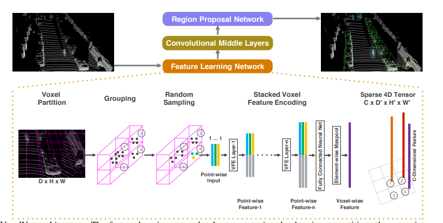 この論文のポイントは点群にPointNet-likeなネットワークで特徴抽出を行った後に、2Dベースのアプローチ(Region CNN)を適応することで物体検出を行います。2D CNNに直接点群を入力すると点群の精微な情報を読み取れないという弱点を最初にPointNetで特徴抽出を行うことで解決したのが進歩性です。
また物体検出自体はCNN系手法の方が精度が高いため、PointNetとR-CNN両方の長所を使っているという意味で興味深い手法です。
Voxelとは?
 左の絵が生の点群データです。
点群データはポイント数が多く扱いにくいので、複数を一纏まりにしたVoxelに変換します。Voxelは粒度によっては点群のように振る舞いますが、荒くすると昔のゲームのポリゴンくらいになってしまいます。
ざっくばらんに言うとはダウンサンプルした点群と捉えることができます。
左の絵が生の点群データです。
点群データはポイント数が多く扱いにくいので、複数を一纏まりにしたVoxelに変換します。Voxelは粒度によっては点群のように振る舞いますが、荒くすると昔のゲームのポリゴンくらいになってしまいます。
ざっくばらんに言うとはダウンサンプルした点群と捉えることができます。
空間的情報を保ったままデータ量、演算量を削減できるため、3D DNNが流行る前から点群の位置合わせ(レジストレーション)を行う際にはボクセル化は定番のアプローチです。
メリット
Voxel間で畳み込みを行うため、後述するPointNetではできない近隣点群間の特徴量も抽出することが可能です。
Voxelの特徴量の他にPoint自体の特徴量抽出も行っているため(直感的には)情報のロスはなく、高精度な認識が期待できます。
PointNetとCNNの良いところどりをしたようなアーキテクチャ。
デメリット
メモリ使用量が多い。
ランダムサンプルやVoxel間隔をチューニングすれば軽くすることは可能だが、チューニングが大変。
公式実装がリリースされていない。
ここに公式では有りませんが実装がありました。
PointPillars: Fast Encoders for Object Detection from Point Clouds
CVPR 2019. https://arxiv.org/abs/1812.05784
- 課題

従来点群のみ使用したネットワークは精度は高いが低速で、点群を画像に投影するネットワークは高速だが 精度が低いという欠点があった。
- 提案
 狙いとしては点群の細かい情報量を失わないように情報量をエンコードし、疑似画像に変換する。その疑似画像を2D CNNで使用するような物体検出ネットワークに入力し、物体検出を行う。
この手法の進歩性は従来単純に点群を俯瞰画像といった疑似画像に投影し物体検出CNNに入力するだけでは点群の細かい情報量が失われてしまっていた。そこで点群を画像に投影するためのエンコードネットワークを用いることで点群情報を失わずに物体検出CNN(SSD)に入力データを与え高精度化を達成した。
狙いとしては点群の細かい情報量を失わないように情報量をエンコードし、疑似画像に変換する。その疑似画像を2D CNNで使用するような物体検出ネットワークに入力し、物体検出を行う。
この手法の進歩性は従来単純に点群を俯瞰画像といった疑似画像に投影し物体検出CNNに入力するだけでは点群の細かい情報量が失われてしまっていた。そこで点群を画像に投影するためのエンコードネットワークを用いることで点群情報を失わずに物体検出CNN(SSD)に入力データを与え高精度化を達成した。
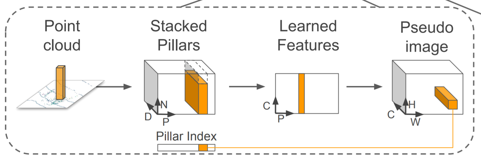 具体的に点群を画像にエンコードするために、Pillar(柱)と呼ぶ点群を細かく格子状に分割しPointNetのような点群DNNを使いPillar内の特徴量を抽出。そして得た2Dの特徴量マップをSSDに与えることで物体検出を行う。
アイデア自体は非常にシンプルながら、PointNetと物体検出CNNを結合する手法を初めて提案し点群物体検出の精度でブレイクスルーを果たした。
具体的に点群を画像にエンコードするために、Pillar(柱)と呼ぶ点群を細かく格子状に分割しPointNetのような点群DNNを使いPillar内の特徴量を抽出。そして得た2Dの特徴量マップをSSDに与えることで物体検出を行う。
アイデア自体は非常にシンプルながら、PointNetと物体検出CNNを結合する手法を初めて提案し点群物体検出の精度でブレイクスルーを果たした。
- 実験
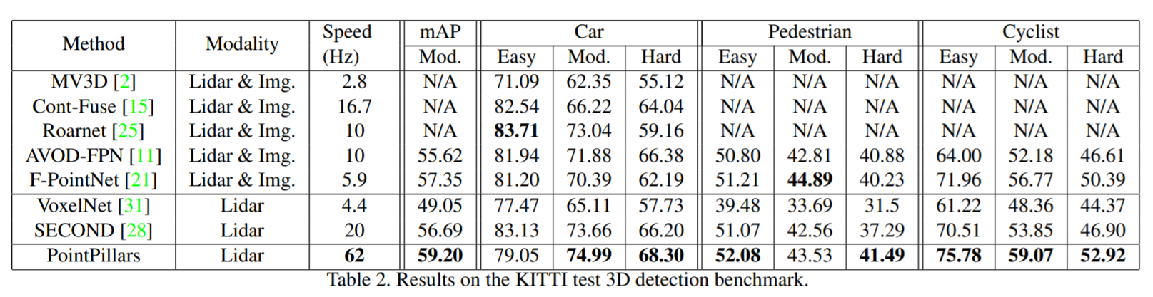 発表当時、KITTIベンチマークでstate of the artを達成。
ネットワーク自身も改造しやすく、Kaggleなどのコンペでも頻繁に使われている。
https://www.kaggle.com/c/3d-object-detection-for-autonomous-vehicles
Class-balanced Grouping and Sampling for Point Cloud 3D Object Detection
https://arxiv.org/pdf/1908.09492.pdf
現在のNuscenes一位のソリューション。

課題 LiDARデータのaugumentationの提案が主に精度向上の要因。 Nuscenesはクラス間精度の平均が評価指標になっているが、学習データ数がクラスによっては異常に少なく学習が進まない。例えば最も頻出する車クラスに対して人やanimalクラスは1/10から1/100しかない。

提案 このようなデータセットインバランスに対応するため、点群データ中に少数クラスを恣意的に生成することで学習を進みやすくした。ネットワーク自体はほぼPointpillarsの応用で、データセット拡張により大幅な精度向上を実現した。また精度に貢献している提案として大きさなどが似ているクラス(人と自転車など)を"superclass"としてまず分類してから詳細クラスを分類する2-stepの分類を実行している。
 特に自転車クラスは14倍も精度向上した。
点群系(3D)のベンチマーク
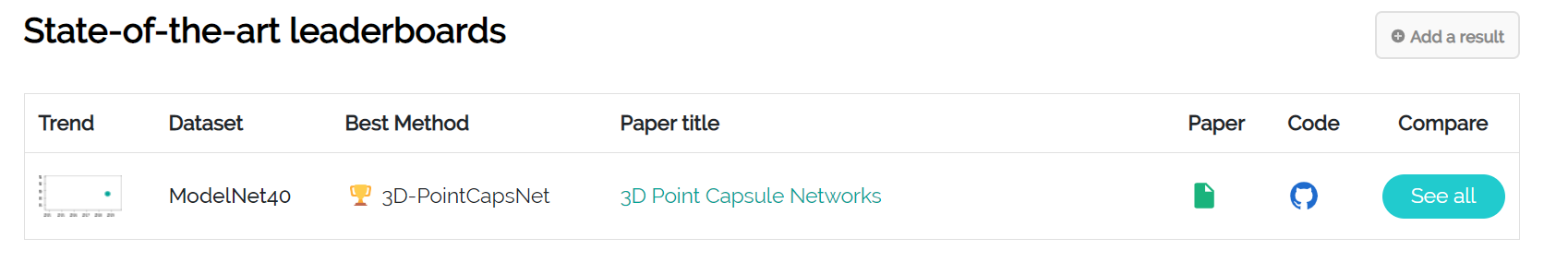
ModelNet40
一番基本的な3D系のベンチマーク。
90%精度が出てしまっているので、モデルがオーバーフィット気味でベンチマークの価値は現在あまりなくなった。MNIST的に学習時間も短いので最初に試すのはこれ。
https://paperswithcode.com/task/3d-object-classification
現在は3D capsulenetがリーダー。
ScanNetv2
現在の室内用3Dデータでは一番難しいタスク。 VoteNetが一位ですね。 https://paperswithcode.com/sota/3d-object-detection-on-scannetv2

自動運転系
nuScenes
 現在では最も難しく、巨大なデータセット。
- 大規模点群+カメラ画像のアノテーション結果
- 20秒で区切られた1000シーンのデータ
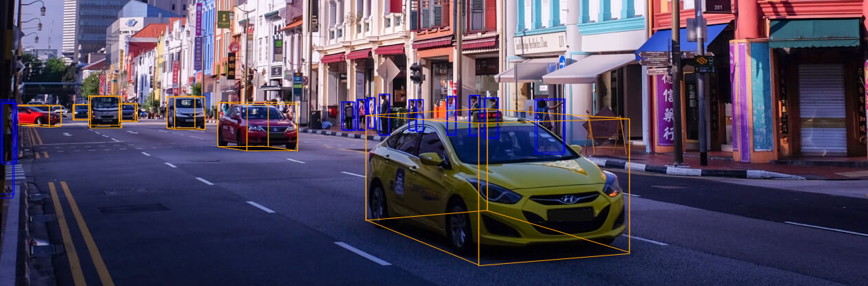
- ボストンとシンガポールの街中
- 23クラスの結果
https://www.nuscenes.org/object-detection?externalData=all&mapData=all&modalities=Any
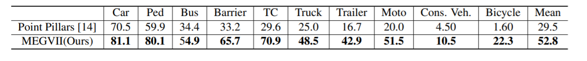
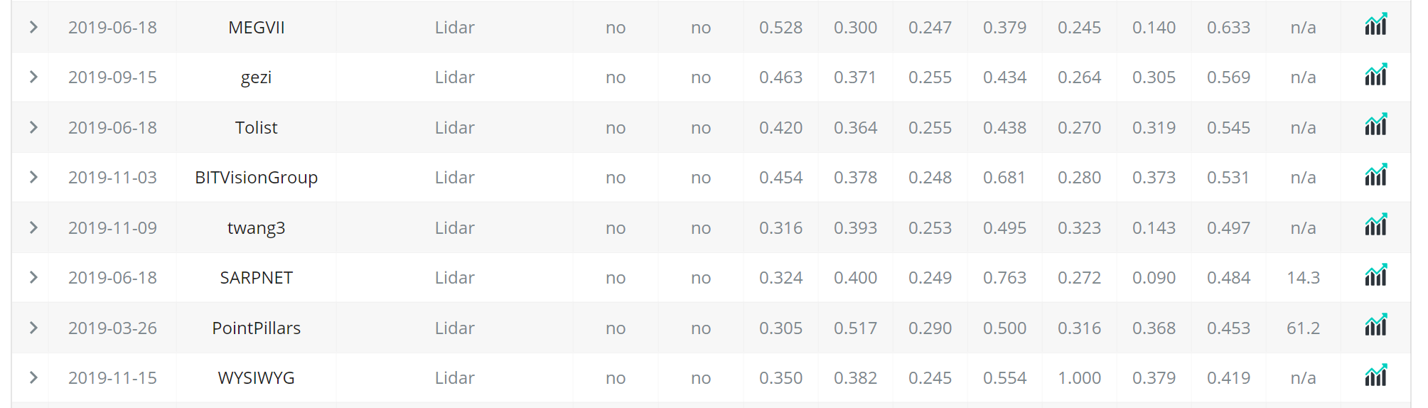 ベンチマーク首位はMEGVIIでPointpillarsは結構精度は低い。
一方でPointpillarsは使いやすく、KaggleのLyftコンペではほとんどの上位陣が使った。
https://www.kaggle.com/c/3d-object-detection-for-autonomous-vehicles
ベンチマーク首位はMEGVIIでPointpillarsは結構精度は低い。
一方でPointpillarsは使いやすく、KaggleのLyftコンペではほとんどの上位陣が使った。
https://www.kaggle.com/c/3d-object-detection-for-autonomous-vehicles
KITTI

従来まで使われていたデータセット。 データ数はあまり多くないが、データセット形式が使いやすくスタートするには最適。 http://www.cvlibs.net/datasets/kitti/
PS
逐次最新論文等は自分のブログにまとめてます。
距離センサ入門(ステレオカメラ、プロジェクション、LiDAR)
Qiitaからのお引越し記事です。
目標
通常のカメラは物体の明るさ、色を抽出するのに対し、距離センサは物体までの距離をセンシングします。そのため3DカメラやDepth Sensorなどと呼ばれたりします。
距離を知ることは多様なアプリケーションにおいて重要であり、例えば自動運転では前方車両までの正確な距離を知ることは必須です。またゲームなどのアプリケーションでは人の動作などを距離センサで抽出するKinectが遊びの幅を広げました。またDaVinciといった手術ロボットでも患部の正確な距離を知るためにも距離センサは重要です。
身近なアプリケーションですと例えば部屋の3Dマッピングなどに使用できます。
部屋の寸法、距離感覚は写真や間取り図にするとイメージが湧きづらいのですが、3Dマッピングしてしまえば部屋そのものを感じることができます。

このようなマッピングは新型iPhone Proで簡単にPolycamなどのアプリを使ってできるのでもしデバイスを持っていたら試してみて下さい!
And the age of 3D scanners in our pockets has begun! The iPhone 12 version of Polycam is now out on the App Store https://t.co/Oih4jQTTEc! Go forth and capture your world 🚀🎥! #iPhone12Pro #iPhone12ProMax pic.twitter.com/JY8LAEi5xk
— polycam (@Polycam3D) 2020年10月23日
この記事では世の中に大きくどのような距離カメラがあるのか、それらの概要や特徴、使用されている製品をリストします。
例えば研究開発プロジェクトに使用する距離センサが選べるようにするのが目標です。
私はLiDARの専門家なのでカメラベースの手法にはあまり詳しくないのですが、使用頻度の高い距離センサであるステレオカメラやプロジェクションカメラについても記述しました。
また点群ディープラーニングについてはこちらをどうぞ。
ステレオカメラ
概要
スバルアイサイトなどに搭載されている市場に多く出回る距離センサです。
またこちらのWhitePaperも参考になります。
Obtaining Depth Information from Stereo Images
https://www.zmp.co.jp/knowledge/adas_dev/adas_sensor/adas_camera/adas_stereo

原理は人間がものを立体的にみるのと同じ原理です。
目を左右交互につむり、モニタを見ると左右にずれるのがわかりますか?
脳はこのずれが大きい物体ほど近くにあり、ずれが小さいほど遠くにあると認識してくれます。これがステレオカメラの原理であり、人間が使っている距離センサもステレオカメラがベースになっているといえます。
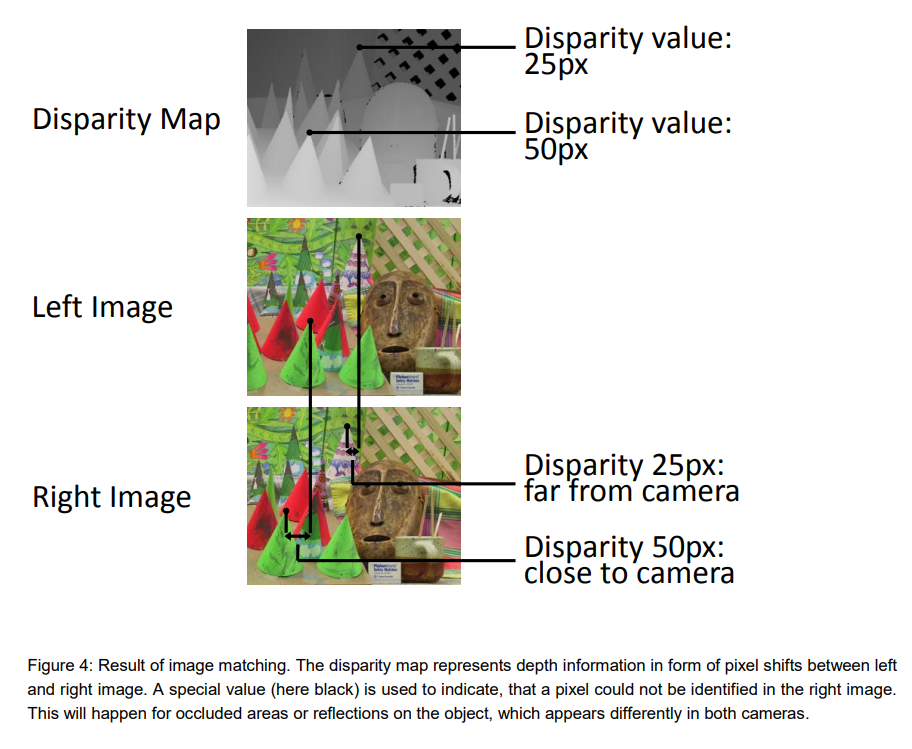
ステレオカメラではピクセルがどれくらいずれた事から、物体までの距離を測ることができます。この際カメラ同士が離れれば離れているほど物体に対してピクセルずれは大きくなるため、正確な距離が図りやすいです。一方でカメラ同士が近いとほとんどピクセルズレが起こらないため、距離を測るのは難しくなります。画素数を向上させれば原理的には測距距離は長くなりますが、信号処理量が指数関数的に増加してしまうのが欠点です。
またステレオカメラ最大のチャレンジは、2つのカメラが同一の物体を見ているかどうかを判定することです。これには高度な画像処理テクニックが必要で、遠くの物体が本当に同一かどうかを当てるのはとても難しくなります。
Reference: Obtaining Depth Information from Stereo Images
またステレオビジョンを適応するには左右の画像間で高低差があってはいけません。 そのため前処理でカメラ歪除去と高低差除去のキャリブレーション(rectify)が必要です。
特徴
他の距離センサは専用部品(レーザなど)が必要な一方で、ステレオカメラは普通の市販カメラを2つ使うだけで実現できるため、コストが安いのが最大のメリットです。
ただ距離を測るために左右のカメラで同一の物体の同じ場所を見る(認識する)必要があり、遠くのものの距離を測るのは難しい。数式などは省略するが、アイサイトのようにカメラを離れて設置しないと遠くのものでは視差が生まれないため、遠くまで見たい場合は筐体が大型化してしまうのが欠点です。
使用製品
1台の PC に4種類の RGB-D カメラをつないで同時キャプチャしてみた。左上 DepthSense DS325、右上 Kinect v2、左下 Kinect v1、右下 RealSense D435。こけて倒したのは D415 (今回は不使用)。 pic.twitter.com/n5h4P2MPZO
— 床井浩平 (@tokoik) 2019年5月30日
市販製品ではIntelのRealSenseがソフトウェア(SDK)もついてきて試しやすいです。
RealsenseD435ならアマゾンで24000円なのでお手軽に購入できます。
https://amzn.to/3tgO9zGamzn.to
RealsenseD435の出力例です。
- 近距離(1-3m)ならば高い精度が取れる
- カメラベースのため、解像度が高い
- CPUでもリアルタイム(30FPS)で動作
のが特徴です。ホビー用途の距離センサならば一番の選択肢だと思います。
RealsenseD400系にはパターンプロジェクションも付いていますが、距離推定に用いているのはほぼステレオカメラです(プロジェクションを切ってもほぼ絵が変わらないためあくまで補助機能ぽいですね。)
パターンプロジェクションカメラ
概要
工業用の高性能3DカメラやiPhoneのFaceIDで使われているのがパターンプロジェクションカメラです。
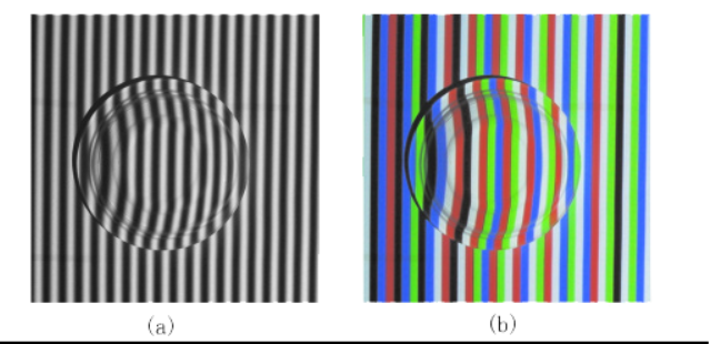
物体に既知のパターンを投影し(パターンプロジェクション)、その歪み方からカメラと物体までの距離を信号処理によって導出します。
説明を聞いてもよくわからないが、下記の図を見るとわかりやすいかと思います。ヘルメットのような物体があるところにしましまのパターンを投影すると、物体の高さによってしましまが歪むことがわかります。このような歪みを読み取り解析することで、ヘルメットの三次元形状を知ることができます。
また下記の動画はiPhoneのFaceIDの仕組みについて解説してます。赤外線で顔中にパターンを放射し、顔の正確な形状を読み取ることができる。凹凸をみているのでFaceIDを騙すのは難しく、セキュリティを強固なものにしていますね。
Using An Infrared Camera To Show How Face ID Works

LiDARに比べると部品がシンプルなため、価格が抑えられるのが特徴。
室内使用であれば非常に高い精度が得られる(mm~um精度)。
一方で外乱の多い屋外使用は厳しい。
またパターンプロジェクションとステレオビジョンを両方使うアプローチは多いです。
ピッキングロボットで頻繁に使用される高精度3DカメラEnsensoではパターンプロジェクションとステレオビジョン両方を備えます。 ステレオビジョンが苦手なマッチングが取りにくい物体(例えば平坦な壁など)でも綺麗に点群を得られるのがメリットです。
使用製品
iPhone

iPhoneの顔認証(FaceID)はアクティブプロジェクションカメラで実現されています。
FaceIDが使われるたびに、iPhoneは赤外線のパターンを放射してます。
実は元の技術はMicrosoft KinectV1を開発していた企業(PrimeSense)をAppleが買収し、発展したものです。 関係者の間ではMiniKinectなどと言われています。。笑
ゾゾスーツ

ゾゾスーツもスーツのドットをカメラで撮影し、距離を測っているという意味で技術的には似ている。ただゾゾスーツはドットを投光していないのでパッシブプロジェクションと言えるかもしれない。人の大体のサイズ感が測れれば良いためか、FaceIDのカメラに比べると点数は少なめ。
工業製品(Ensenso, キーエンス)
How to reconstruct objects with an Ensenso 3D camera and data comparison using HALCON image processing: 3D image processing detects irregularities or minimal deviations that are not even visible to human eyes. #demo #objectverification #3Dvision #qualitycontrol #industry40 pic.twitter.com/3p4EEurOUW
— IDS Imaging Development Systems GmbH (@IDS_Imaging) 2018年8月9日
工業用途のセンサ出力例はあまりネットに出回ってないのですが、mm精度が得られRealsenseなどとは精度自体は比べ物になりません(そんなのホビー用途ではオーバースペックなんですが)
一つ数百万円します笑
工場内の検品やロボット製品に使われることが多いです。産業系の展示会に行くとこいつが付けられていることが多いので探してみて下さい笑
一方でプロジェクションを正確に読み取れるのは数メートル範囲内のみであり野外の使用などは厳しいです。基本的には室内用ですね。

キーエンス 3Dカメラ

Ensenso X36
Time of Flight LiDAR
Time of Flightの原理
カメラベースの距離センサ(ステレオカメラ、プロジェクション)とLiDARは原理が根本的に異なる。
一方でLiDARはTime of Flight(光の飛行時間)をベースにして距離を測ります。
原理としては単純で、下記の図のようにレーザ光を筐体から放ち、そのレーザが物体に反射して返ってくるまでの時間を計測する。もしレーザ光が10秒後に返ってきて光速を単純のため1m/sとすると、物体までの距離は
(10秒 * 1m/秒)/2 = 5m
と5m先に物体があることがわかります。このように飛行時間をベースにして距離を導出する手法をTime of Flightと呼びます。
実際の光速は108m/sと非常に早いため、光が返ってくるまでの時間は数ピコ秒、ナノ秒のオーダーなので時間を計測する回路には高い精度が求められます。
このようなレーザパルスの帰還時間を直接測定するタイプのLiDARはdirect Time of Flight sensorとも呼ばれます。
https://tech.nikkeibp.co.jp/atcl/nxt/column/18/00001/02023/?ST=nnm
特徴
LiDARの最大の特徴は
- 高精度
- 遠距離
- 外乱に強い(野外で使用可)
- 値段が高い
と挙げられます。強いパルスレーザ光を照射し、その帰還時間から直接距離を導出するため誤差が混入しづらく信頼性が高いのが特徴です。これらの特徴はカメラベースで実現するのは難しいため、過酷な条件でも動作が義務付けられる自動運転ではLiDARが主に遠方の物体検出で使われることが期待されています。
一方でスキャン機構、レーザ出射機、レーザ受光部と多くの専門素子が必要になるためカメラ型に対してコストは数倍~数十倍高くなってしまうのはデメリットです。
最近はLivoxなど10万以下のLiDARが多くのプロトタイプで使用され始めているので値段が高いから敬遠される時代は終わりつつあるかも知れません。
Livox全ラインナップに対応した低速(<30km/h)Slamを公開しました。先日公開した高速SLAMはHorizonのIMU情報を使っていますが、本プログラムは点群だけで計算する汎用型です。低速AGV、マッピング、AR、VR等の開発にご利用ください。https://t.co/LKLGZYPTYA pic.twitter.com/zTnn2wYbZP
— Livox_JAPAN (@LivoxTech_JP) 2020年6月29日
Livox Detection V1.1がリリース!Horizon*6+TELE-15*1で収集した360度の点群を元に、人、二輪、乗用車、トラック、バスの対象物をセグメンテーション。V1と比較すると、距離レンジが2倍に、左右、後方の識別率がアップ!https://t.co/XQhnwiEPNh#AGV #自動運転 #Lidar #AI #識別 pic.twitter.com/UskzD0SQfu
— Livox_JAPAN (@LivoxTech_JP) 2020年12月10日
この図のような長距離(100-200m)の精微な点群(Point Cloud)でスキャンできるのはLiDARの最大のメリットです。
野外で遠距離までバッチリ点群を取れる距離センサはLiDARだけです。なので自動運転などで熱い期待を持たれています。(TeslaなどLiDARいらないよ派もいますが。。)
スキャン型LiDAR
LiDARのの上記のTime of flightの原理で1画素あたりの距離を取得することはできます。それでは絵として距離情報を得るためにはどうしたら良いのでしょう?そのための工夫としてLiDARにはスキャンという概念があります。
一つのアプローチはミラーを使い、出射するレーザ光を走査(スキャン)する方法です。
https://commons.wikimedia.org/wiki/File:LIDAR-scanned-SICK-LMS-animation.gif
上記のアニメーションはミラーを使ったLiDARのスキャンをわかりやすく表しています。ミラーを回転させることでレーザ光を360度走査し、周辺環境の全ての情報を得ることができます。
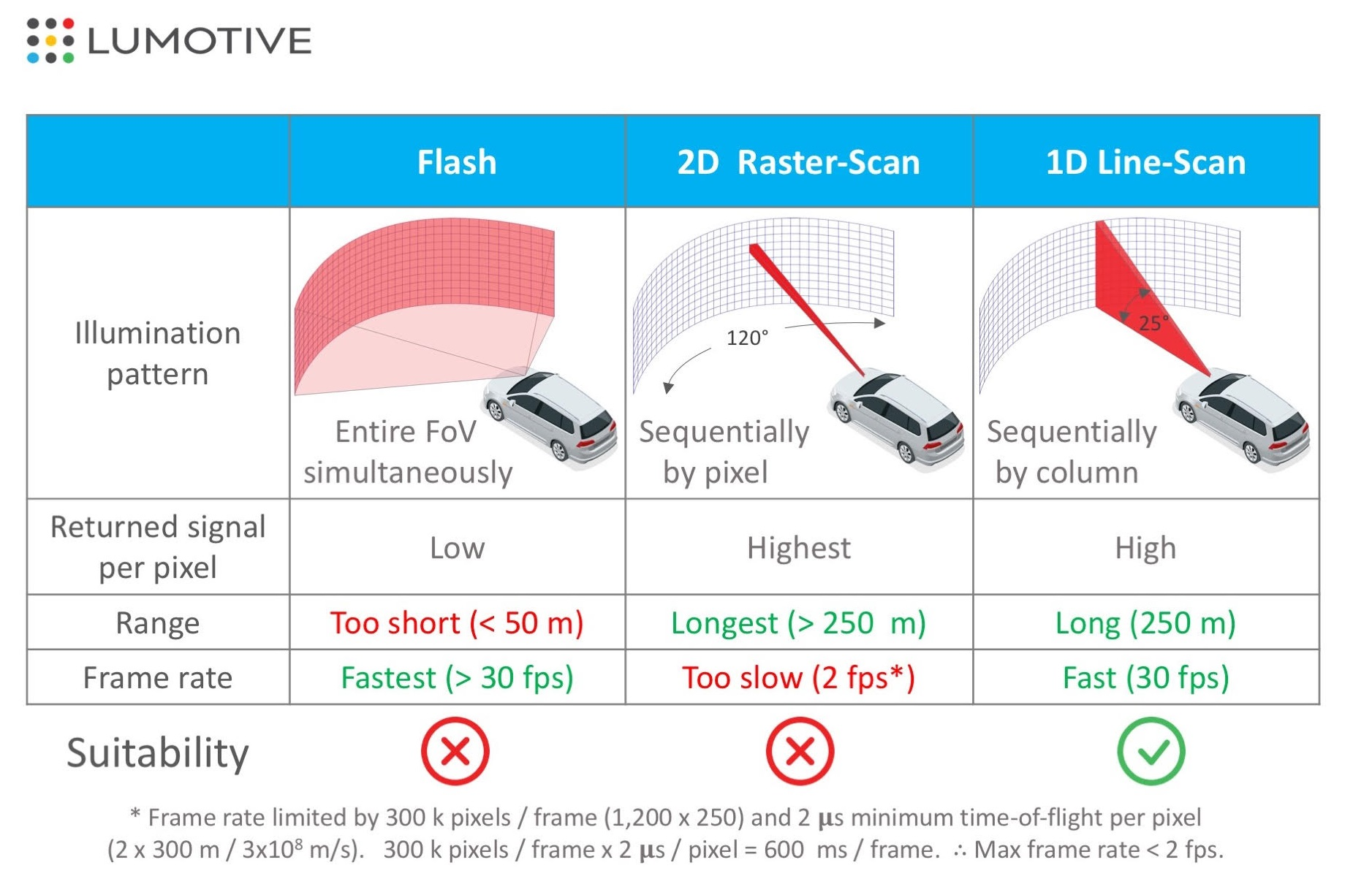
このとき1画素ずつ情報を得ながら二次元的にスキャンするのが2Dラスタースキャンという方式で、縦画素を一気に取得しながら横方向にスキャンする方式を1Dスキャンと呼びます。両者とも距離は出ますが、1Dスキャン法が距離画像を得るために必要な時間が短いため、高いFPSを達成しやすいです。
一方でミラーを使うと(一眼レフカメラのように)LiDARの筐体は大きくなってしまいます。そのためミラーを使わずにMEMSミラーを使ったり、光学的にスキャンするOptical Phased Array LiDARなども開発が活発に進められており、将来的にLiDARの小型化や低コスト化は進むと見られています。
フラッシュ型LiDAR
またスキャンをせずにカメラのイメージセンサのように二次元画素情報を一度に取得するようなLiDARも開発されています。イメージセンサ全体を覆うようなレーザ光を出射し、それを受光するだけなので構造的には非常に単純です。そのためスキャン型に比べ低コストで実現可能です。
一方で課題はいくつかあり、 - 1画素あたりのレーザパワーが少ないため距離が短い - 外乱に弱い - 干渉などに弱く、ノイズが発生しやすい というのが欠点のため自動運転には適さないが、室内のロボットなどには活かせるかもという感じです。
製品
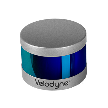
Velodyne Series
最も有名なToF LiDARはVelodyneの製品でないでしょうか。LiDAR製品を初めて世に出したメーカーで現在も帝王として君臨しています。
彼らの製品は数十万~数百万と非常に高額ですがそのクオリティは一級品。Velodyneを使っていない自動運転車はTeslaとWaymoくらいだと思います(Waymoは独自LiDARを使用)。ロボットの研究開発の現場でも画素数や精度が高いため、Veloが使われることが多いイメージです。
追記 Livox Horizon
DJIの子会社であるLivox社が10万円を切りつつも高精度を達成するLiDARを発売しており、こちらがロボ系プロジェクトでは主流になりつつあります。
アマゾンで買えます笑
クオリティは凄まじく、SDKなどgithubで公開してくれてるので開発もしやすいです。Velodyneから乗り換えている人多数ですね。
iPhone
iPhoneのフロントには実は結構昔からToF LiDAR(1画素)が搭載されています。
スキャンなどはしないので低コストなのでしょう。
画像で言うProximity Sensorがそうです。 通話する時、iPhoneの画面を顔に近づけると画面は自動的に切れます。これは顔とiphoneとの距離をセンシングしているからだと思います。
追記:iPhone, iPad ProはdToF LiDARを搭載しました。 詳しくは:こちら記事参照
iToF LiDAR
Azure Kinectなどに搭載されている技術です。
Maskをopencv使って縮小する
目的
このようなMask画像を画像に対して縮小したいというマニアックな事例の備忘録。
これを

こうする

パイプライン
マスクの中心を計算
# 重心を取得
m = cv2.moments(mask)
cx = int(m['m10'] // m['m00'])
cy = int(m['m01'] // m['m00'])
print(cx, cy)
中心に画像をオフセット
Affine変換で画像を平行移動させる。
# 中心にmaskをシフト
num_rows, num_cols = mask.shape[:2]
# Create translation matrix
offsetx = mask.shape[0]//2-cx
offsety = mask.shape[1]//2-cy
translation_matrix = np.float32([ [1,0,offsetx], [0,1,offsety] ])

# Image translation
mask_translation = cv2.warpAffine(mask, translation_matrix, (num_cols,num_rows))

mask全体を縮小
# maskを半分に縮小
mask2 = cv2.resize(mask_translation, None, fx=0.5, fy=0.5, interpolation=cv2.INTER_LINEAR)
mask_resized = cv2.copyMakeBorder(mask2, 200, 200, 200, 200, cv2.BORDER_CONSTANT, 0)

オフセット分を戻す
# オフセットを戻す
translation_matrix = np.float32([ [1,0,-offsetx], [0,1,-offsety] ])

# Image translation
mask_translation = cv2.warpAffine(mask_resized, translation_matrix, (num_cols,num_rows))
plt.imshow(mask_translation)
有名なDeep Learningの特許を調べてみた
目的
有名所のDNN特許を調べてみました。ほとんどがGoogleの特許ですがBatchNorm、transformer以外日本で登録されていないのが多いですね。 調べたところで力尽きてちゃんとクレームはトップ以外読んでません。随時リストはアップデートしていきます。
参考: https://www.reddit.com/r/MachineLearning/comments/c5mdm5/d_googles_patent_on_dropout_just_went_active_today/www.reddit.com
感想
Dropout,Batchnorm,transformerなど根幹特許を多くGoogleに抑えられていますが、基本的にはPatent Trollに対しての防衛でGoogleから権利行使することはないようです。(訴訟は今の所ない)
Tips
特許の状態は大きく分けて3つあります。
出願:特許庁に特許を提出した段階です。この段階では特許内容を他社が読むことは出来ません。
公開: 2年立つと特許は公開されます。この段階では特許内容を他社が読むことは出来ますが、まだ法的に特許は有効ではありません。
登録: 審査官が許可を出すと特許は登録され、特許として効力を持ちます。
ちなみに論文と同じで特許は審査官に拒絶されることもあり、最大2度ほど修正の機会が与えられます。
画像認識
Inception方式のDNN
patents.google.com クレーム:インセプション方式のDNN
Assignee:Google
Status:登録
日本:なし
Faster-RCNN
クレーム: 2-stageの物体検出器(Fast-RCNN方式)
Assignee:Microsoft
Status:登録
日本:なし
学習系
hirotaka-hachiya.hatenablog.com
Dropout
patents.google.com クレーム:Dropout正則化を用いて学習されたモデル
Assignee:Google
Status:登録
日本:なし
Batchnorm
トップクレーム範囲:BatchNormを用いて学習されたモデル
Assignee:Google
Status:登録
日本:あり

登録国がこの特許だけ異様に多いことからGの本気度が伺えます。
学習並列化
patents.google.com クレーム:並列化を用いて学習されたDNNモデル
Assignee:Google
Status:登録
日本:なし
蒸留
patents.google.com Assignee:Google
Status:登録
日本:なし
Neural Architecture Search (NAS)
Assignee:Google
Status:登録
日本:なし
NLP
Transformer
Transformer も日本含め公開されてると思われますね。。。(つまりViT系は…)https://t.co/0AcakhQPE0
— ふぁむたろう (@fam_taro) 2021年1月25日
Assignee:Google
Status:US 登録
日本:あり
 この特許も当たり前ですが出願国が多く、本気ですね。
word2vec
patents.google.com Assignee:Google
Status:登録
日本:なし
GAN
Spectral Normalization
patents.google.com Assignee:PFN
Status:公開
日本:あり
Pytorch高速化 (3) TensorRTで推論を10倍高速化
TLdr;
torch2trtというpytorchモデルをTensorRTに簡単に変換するライブラリを使い、Jetson nano+xavier上で画像認識とセグメンテーションの推論処理を10倍高速化できることを確認しました。
ただtorch2trtはカスタムモデルには対応していないため(resnetなどtorchvision標準モデルのみ)、自作モデルのTensorRT変換は大変だと思います。
他高速化シリーズ aru47.hatenablog.com
TensorRTとは

例えばJetsonNanoなどは安価に入手できるエッジデバイスだが搭載しているGPUはローエンドなため大きい画像をリアルタイムで処理するのは難しい。
一般的なpytorch推論は
model.eval()
with torch.no_grad():
        for (data, target, _, _) in tqdm(loader):
            # data = data.half().cuda() # 半精度推論
            logits = model(data)
と書けるが、これでも速度が不十分なことが多い。
TensorRTはnVidiaが提供している推論を高速化させるフレームワークである。モデルをTensorRTで走らせる事でエッジデバイスでも高速な推論が可能となる。
その機能の一つとして強力なものにグラフ最適化というものがある。
図はInceptionモジュールのものであるが、通常のpytorch等はconv、relu、batchnormと3ステップ別々の計算を行う。
ここで入出力のテンソルは毎回メモリから読み書きする時間も必要であり、計算時間は長くなってしまう。
そこでTensorRTのグラフ最適化(レイヤフュージョン)はDNNではCNN, relu, batchnormと3ステップ計算が頻出することを利用し、その計算をまとめた専用レイヤーを用意する。
そうすることでデータ読み書きと演算はあたかも1度しか行わずにconv、relu、batchnormの計算を実行することができる。reluやbatchnormは単純な加算、クリッピングで表現できるため計算をまとめることは容易である(カーネルを用意さえあれば)。

例えばresnet50では等価的にレイヤ数を1/4に削減している。 この最適化は非常に強力であり、大幅な高速化が可能となる。
またPytorchでは対応していないINT8のTensorCoreを使った計算もTensorRTならば可能である。 FP16に対しメモリ量が半分になるため、データ伝送も2倍高速化することが期待できる(実際に大幅に高速化可能)
またTensorRTはV100などの一般的なGPUでも高速化が可能であり、10倍ほどの高速化が公式スライドで報告されている。

TesnorRTを気軽に試す
TensorRTを自分のネットワークに試すにはPytorchモデルをONNXフォーマットに変換→ONNXのモデルをTensorRTで読み込むというフローがあるが、ONNX変換はクセが強く、気軽に試すのは難しい。
そのためnvidiaの出しているtorch2trtという変換ツールを使うことでONNXを介さすに直接PytorchモデルをTensorRTに変換できます。 ただtorch2trtは対応しているレイヤは標準CNNのものがほとんどで(Resnetなど)、カスタム関数などが入っていると上手く変換はできませんでした。 例えば物体認識モデルの変換は難しいです。その場合は公開されているONNXモデルを使うのが良いです。
以下レポでtensorRTをJetson上で試し、速度向上効果を見てみました。
TensorRT化はモデルと入力画像サイズを渡すことで簡単にできます。
 # define input
 input_size = [1, 3, 256, 256]
 x = torch.zeros(input_size).cuda()

# convert to tensorrt models
model_trt = torch2trt(model, [x], fp16_mode=True, int8_mode=True, max_batch_size=1) # 精度によってモード切り替え
詳しい使い方はレポかtorch2trtのページを読んでみて下さい。
画像認識
| resnet18 | resnet34 | resnet50 | |
|---|---|---|---|
| Raw | 11 | 12 | 16 |
| FP32 | 3.8 | 5.6 | 9.9 |
| FP16 | 2.1 | 3.3 | 4.4 |
| INT8 | 1.7 | 2.7 | 3.0 |
Xavier上で数種類のネットワークの画像一枚に掛かる時間を調べました(ms)。rawはpytorchそのままで他はtensorRTで記載分解能で量子化したものです。NanoではInt8が何故か動きませんでした。 画像サイズは256x256.
画像セグメンテーション

| fcn_resnet50 | fcn_resnet101 | deeplabv3_resnet50 | deeplabv3_resnet101 | |
|---|---|---|---|---|
| Raw | 200 | 344 | 281 | 426 |
| FP32 | 173 | 290 | 252 | 366 |
| FP16 | 36 | 57 | 130 | 151 |
| INT8 | 21 | 32 | 97 | 108 |
こちらはセグメンテーションの結果です。画像サイズは512*512と大きく、量子化を積極的にやることで速度が大幅に上がることがわかりました。
Github Actionsでpypiのパッケージを発行
なぜgithub actionsで発行できると楽か

自作ライブラリ開発しているとすると普通ならコーディング、setup.pyを記述、pypiにtwineでアップロードという流れになります。 blog.amedama.jp
ただこのpypiへのアップロードが意外に面倒くさい。。!毎回pypiアカウントの認証などしなくてはならず、ライブラリ発行が億劫になるため出来るなら自動化したいものです。
Github actionsを使うとgithub上でリリースを追加することで自動的にpypiにアップロードすることができ非常に便利だったのでその方法を記述します。
やってみた
他レポの見様見真似でやってみた。
Pypiに書いてあるフローは以下であるが、微妙に今回参考にした設定とは異なる。
今回用いたライブラリは自分で開発しているkaggle用TTAライブラリであるodachです。
Github actionsの設定ファイルを追加
レポ下に.github/workflows/python-publish.yml
を追加します。
# https://github.com/kentaroy47/ODA-Object-Detection-ttA/blob/main/.github/workflows/python-publish.yml
name: Upload Python Package

on:
  release:
    types: [created]

jobs:
  deploy:
    runs-on: ubuntu-latest
    steps:
    - uses: actions/checkout@v2
    - name: Set up Python
      uses: actions/setup-python@v2
      with:
        python-version: '3.x'
    - name: Install dependencies
      run: |
        python -m pip install --upgrade pip
        pip install setuptools wheel twine
    - name: Build and publish
      env:
        TWINE_USERNAME: ${{ secrets.PYPI_USERNAME }}
        TWINE_PASSWORD: ${{ secrets.PYPI_PASSWORD }}
      run: |
        # ソース配布型
        python setup.py sdist bdist_wheel
        twine upload dist/*
Pypiの認証情報をSecretsに追加
レポジトリのSettings以下のSecretsにpypiの認証情報を追加します。
PYPI.PASSWORDとPIPY.USER_NAMEにそれぞれpypiのユーザ、パスワードを格納します。secretsの情報は管理者しか見られないため安心です。

Githubにリリースを追加
ここまででgithub actionsの準備は整いました。releaseを追加すればactionが走り、その結果をActions以下で確認できます。

無事に走ればpypiにもパッケージが追加されているのを確認できます。
